Bump/Parallax Mapping -anyone have a working GLSL example?

All topics about ZGameEditor goes here.

Moderator: Moderators

User avatar
jph_wacheski
Posts: 1005
Joined: Sat Feb 16, 2008 8:10 pm
Location: Canada
Contact:

Post by jph_wacheski »

yeah I have looked a Blender a bunch of times and just never invested the time to learn it,. may do eventually as when I saw Okkuplektor by 0rel where he used it as level design tool with some export scripts he wrote, I was again interested!,. I will look into those cheaper apps as well,. danm you seem to be way up on the tech. quite the little knowlage factory between your ears eh?

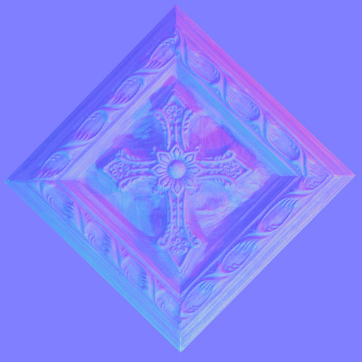
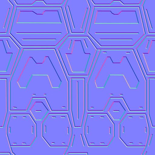
As far as bump mapping I think normals have more detail and directionality,. but I will try to get a bump working too to compare,. but so far I think the normals will be usefull to me,. even if I use Werk for bitmaps., (bloating my file size :( ) see example; I included the .k file to show how simple normal gen. can be,. and it do look nice running in the zge.

Yes, I had found one for Parallax as well,. just not working just yet,. have a look and see if you can get it running. http://www.dhpoware.com/demos/glslParal ... pping.html
Attachments
normal_generation_001.zip
zip file with .zgeproj and .k
(282.86 KiB) Downloaded 568 times
iterationGAMES.com
User avatar
Kjell
Posts: 1883
Joined: Sat Feb 23, 2008 11:15 pm

Post by Kjell »

Hmm,

What on earth is a .k file? :roll:

Both the imported Normal Map and the generated don't look right I'm afraid. Keep in mind that 3 axis are Red at 90 deg ( -1 to 1 range, so bitmap 0 to 1 ), Green at 210 ( -1 to 1 range, so bitmap 0 to 1 ) and Blue at 330 ( 0 to range, so bitmap 0.5 to 1 ).

So under all normal circumstances they look fairy blue-ish.

Image
Image
Image

And a height map actually holds more data then a normal map ( since it's used in just 1 dimension ).

K
kattle87
Posts: 402
Joined: Wed Sep 26, 2007 9:06 am
Location: Italy

Post by kattle87 »

blue is @ 330... this is what I was missing. Thank you Kjell. Heightmap2Normal bitmap ready within 1 hour.
Wait... 0 to 1 range? :D why? :D
In the fall of 1972 President Nixon announced that the rate of increase of inflation was decreasing. This was the first time a sitting president used the third derivative to advance his case for reelection.
-=Hugo Rossi=-
User avatar
Kjell
Posts: 1883
Joined: Sat Feb 23, 2008 11:15 pm

Post by Kjell »

Hmm,

Or the other way around .. green at 330 / blue at 210 .. which is what I had initially, but then changed it because I wasn't sure.

Pixel values are limited between 0 - 255 ( 1 in ZGE ). Not sure if this also goes for the internal ZGE bitmap format ( at least within a BitmapExpression you can go beyond those values ), but it's certainly true for the .bmp format. In order to use the data correctly in a shader you then need to divide by 2 and subtract 1.

.. still not sure :P

K
kattle87
Posts: 402
Joined: Wed Sep 26, 2007 9:06 am
Location: Italy

Post by kattle87 »

http://www.blender.org/development/rele ... rmal-maps/
they states that the blue has another meaning ^^ I will see what I came up with!
In the fall of 1972 President Nixon announced that the rate of increase of inflation was decreasing. This was the first time a sitting president used the third derivative to advance his case for reelection.
-=Hugo Rossi=-
User avatar
Kjell
Posts: 1883
Joined: Sat Feb 23, 2008 11:15 pm

Post by Kjell »

Hi Francesco,

You're right, I asked a fellow coder and he said there are a couple of different implementations. Some don't use the blue at all, others use Red as X, Green as Y and Blue as Z coordinates. Since you define how the data should be used in the shader yourself you can decide for yourself.

Anyway, why aren't we talking about collisions / physics instead :wink:

K
kattle87
Posts: 402
Joined: Wed Sep 26, 2007 9:06 am
Location: Italy

Post by kattle87 »

First "normal" try... Actually this was mostly guesswork.
How to use it: create a color map and a height map. Then, load the heightMap into the H2N (Height to Normals) Bitmap, and use it with the shader.
Actually, I hardcoded the bitmap size into the component. It's 256. If you need, you can easily changing it and don't forget to replace the "255" with what fits your new choice (EG: 511 for 512x512 or 63 for a 64x64)

It seems to be working, at least. It surely can get better ^^
Attachments
normal_generation_003.zgeproj
(4.78 KiB) Downloaded 568 times
In the fall of 1972 President Nixon announced that the rate of increase of inflation was decreasing. This was the first time a sitting president used the third derivative to advance his case for reelection.
-=Hugo Rossi=-
User avatar
jph_wacheski
Posts: 1005
Joined: Sat Feb 16, 2008 8:10 pm
Location: Canada
Contact:

Post by jph_wacheski »

HA, nicely done bro!
iterationGAMES.com
User avatar
Rado1
Posts: 775
Joined: Wed May 05, 2010 12:16 pm

Post by Rado1 »

Hi Kjell, all,

I tried your bump shader, but the problem is that the shader cannot access attribute variable vTangent. AFAIK, attribute variables should be set in OpenGL application and your ZGE projects do not do that. How this shader could work with ZGE? Maybe the problem is in my GPU, because ZGE tells "GL shaders: 1.20".

As a dirty, maybe not 100% correct, workaround to obtain the tangent vector by:

Code: Select all

vec3 vTangent = cross(vec3(1.0,0.0,0.0), gl_Normal);
Any comments/explanations are welcome. Thanks.
User avatar
Kjell
Posts: 1883
Joined: Sat Feb 23, 2008 11:15 pm

Post by Kjell »

Hi Rado1,
Rado1 wrote:I tried your bump shader, but the problem is that the shader cannot access attribute variable vTangent.
That shader wasn't mine .. i simply copy pasted the example jph linked to in the original post :)
Rado1 wrote:AFAIK, attribute variables should be set in OpenGL application and your ZGE projects do not do that.
Correct .. the project doesn't seem to work properly anymore with the current version of ZGE though, so something must have changed during the years ( since the exe build with a older ZGE does still work ). Anyway, ZGE doesn't support custom vertex formats, so either you have to "sacrifice" one of the attributes for the tangent data, or you need to use OpenGL calls.

K
User avatar
VilleK
Site Admin
Posts: 2277
Joined: Mon Jan 15, 2007 4:50 pm
Location: Stockholm, Sweden
Contact:

Post by VilleK »

It is strange because ZGE has never sent any attribute vTangent data so I'm not sure how this could have worked before. With the new programmable pipeline I've been planning that ShaderVariable.ArrayKind could be set to "attribute" so that we can send in various attribute data at runtime. Would that be a good solution?
User avatar
Rado1
Posts: 775
Joined: Wed May 05, 2010 12:16 pm

Post by Rado1 »

VilleK wrote:I've been planning that ShaderVariable.ArrayKind could be set to "attribute" so that we can send in various attribute data at runtime. Would that be a good solution?
This seems to be a good solution. vec* types should be added to the array kind list.
User avatar
Kjell
Posts: 1883
Joined: Sat Feb 23, 2008 11:15 pm

Post by Kjell »

:(
VilleK wrote:It is strange because ZGE has never sent any attribute vTangent data so I'm not sure how this could have worked before. With the new programmable pipeline I've been planning that ShaderVariable.ArrayKind could be set to "attribute" so that we can send in various attribute data at runtime. Would that be a good solution?
No, that would be a bad solution. You really want to do this the right way ... both to not ruin the current Mesh components, but also for future support for weights / morph-targets in mind. We discussed this briefly some time ago ..
VilleK wrote:The problem with using several textures is that there is currently no way in ZGE of specifying separate coordinates of the other textures. So at the moment you need generated coordinates to make the other textures show. We could add something to MeshExpression to allow writing to several set of coordinates.
Kjell wrote:The easiest ( but worst? ) solution would be to add a additional HasTex2Coords / HasTex3Coords checkboxes to MeshExpression. A more flexible approach would be to add a Attributes node to a Mesh allowing to add additional attributes to the standard ones. Even more powerful would being able to define a exact vertex attribute specification, but not sure that can be implemented without breaking backwards compatibility.
K
User avatar
VilleK
Site Admin
Posts: 2277
Joined: Mon Jan 15, 2007 4:50 pm
Location: Stockholm, Sweden
Contact:

Post by VilleK »

Well I'm glad we have a consensus :lol: ;)

Kjell can you explain a bit more? Can you give an example with suggestions for names of Components and Properties needed to achieve your idea?
User avatar
Rado1
Posts: 775
Joined: Wed May 05, 2010 12:16 pm

Post by Rado1 »

I just realized that attribute value is per vertex, therefore, shader variable marked as "attribute" will not be sufficient; it can be used for attribute declaration at most. However, it could be unintuitive and attribute variables should be defined somewhere else (currently, only in expressions using e.g. glGetAttribLocation). I would suggest another section of Shader component comprising AttributeVariable components with name, type and id/index (index returned by glGetAttribLocation).

There should be some way to define attributes for vertices, e.g., in definitions of meshes. For instance, in MeshExpression to use array A[attribute_index] for specifying attribute value. attribute_index is id of attribute returned by glGetAttribLocation. For now, we have the only possibility - to use glVertexAttribPointer with arrays, which works, but is not very convenient.

vec* types can be added for uniform variables anyway.
Post Reply